
Table of Contents
We recently onboarded to a different GPU cluster to train our LLMs, and were hitting 1 iteration/second on a single GPU node, but after scaling up to 2 nodes with data parallelism, we started hitting 0.2 iterations/second. We reached out for the documentation, and saw a list of variables to export, e.g.:
export PMIX_MCA_psec=^munge export NCCL_IB_HCA=mlx5_0,mlx5_3,mlx5_4,mlx5_5,mlx5_6,mlx5_7,mlx5_8,mlx5_9 export MELLANOX_VISIBLE_DEVICES=allexport UCX_NET_DEVICES=mlx5_0:1,mlx5_3:1,mlx5_4:1,mlx5_5:1,mlx5_6:1,mlx5_7:1,mlx5_8:1,mlx5_9:1export NCCL_SOCKET_IFNAME=bond0.2102
Unfortunately, the settings did not help, and we were stuck. Worse, we were paralysed by the deluge of settings and did not know where to begin debugging. We even observed that mlx5_bond_0 (LID=0) crashed NCCL — LID 0 is invalid, and the kernel rejects the ibv_modify_qp call with EINVAL.
This sent us down the rabbit hole to first understand what each of the terms we were exporting mean. Hence this guide.
1. The Problem
Distributed training splits a model's workload across multiple GPUs. After each forward/backward pass, every GPU must exchange gradient data with every other GPU — an operation called allreduce. The speed of allreduce directly determines training throughput.
Within a single node, GPUs talk over NVLink (about 450 GB/s per direction per GPU). Across nodes, GPUs talk over InfiniBand RDMA (about 50 GB/s per Host Channel Adapter (HCA), about 400 GB/s aggregate with 8 HCAs). HCA is the Infiniband network card. The software library NCCL decides which path to use and manages the data movement. If either path is misconfigured, performance silently degrades by 10-100x.
2. Physical Hardware
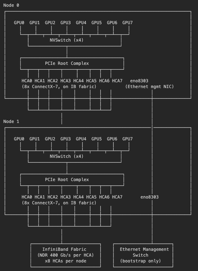
Each node has:
8x NVIDIA H200 GPUs with 141 GB HBM3e each, interconnected by NVLink
4x 3rd-gen NVSwitch chips providing all-to-all GPU connectivity
8x NVIDIA ConnectX-7 HCAs (mlx5 driver; 1 PIX-affine HCA per GPU) for InfiniBand
1x Ethernet NIC (eno8303) on a separate management network
The InfiniBand fabric and Ethernet management network are physically separate networks.
3. Intra-Node Communication: NVLink
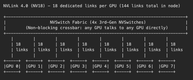
NVLink is a direct GPU-to-GPU interconnect that bypasses PCIe entirely. On H200 systems, NVSwitch chips act as crossbar switches — each GPU's 18 NVLink connections plug into NVSwitch, which dynamically routes traffic so any GPU can talk to any other GPU at full bandwidth. This is not point-to-point wiring between GPU pairs; NVSwitch provides all-to-all connectivity. A DGX H100/H200 has 4x 3rd-gen NVSwitch (64 NVLink ports each).
Bandwidth math:
Each NVLink link: 50 GB/s bidirectional (25 GB/s per direction)
18 links per GPU: 900 GB/s bidirectional total, 450 GB/s per direction
NVSwitch routes all 18 links dynamically — any GPU can reach any peer at full bandwidth
Allreduce BusBW ceiling (ring): 450 GB/s (unidirectional, see section 9 caveat)
NVLink is only available within a single node. For cross-node communication, data must leave the GPU, traverse PCIe, and go out through an InfiniBand HCA.
4. Inter-Node Communication: InfiniBand and RDMA
What is InfiniBand?
InfiniBand (IB) is a high-performance network fabric designed for low-latency, high-bandwidth communication. Unlike Ethernet (which carries TCP/IP packets through a general-purpose OS networking stack), IB supports RDMA — Remote Direct Memory Access.
What is RDMA?
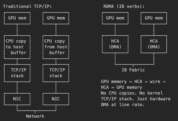
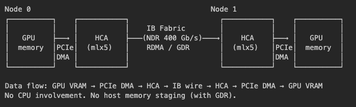
RDMA lets one machine read/write memory on another machine without involving either CPU. The network adapter (HCA) performs the transfer autonomously using DMA:
GPU Direct RDMA (GDR)
GDR takes RDMA one step further: the HCA reads/writes directly from GPU memory over PCIe, skipping host RAM entirely. Without GDR, data would stage through host memory (GPU → CPU RAM → HCA), adding an extra copy. Disabling GDR costs 3x bandwidth in our tests.
InfiniBand Addressing: LID, QP, GID, pkey
IB has its own addressing scheme:
| Concept | What it is | Analogy |
|---|---|---|
| LID (Local Identifier) | 16-bit address assigned by the subnet manager to each IB port | Like an IP address, but for the IB fabric |
| QP (Queue Pair) | A connection endpoint — one send queue, one receive queue | Like a TCP socket |
| GID (Global Identifier) | 128-bit globally unique address (includes port GUID) | Like a MAC address |
| pkey (Partition Key) | Access control — only ports with matching pkeys can communicate | Like a VLAN ID |
To send data between two GPUs on different nodes, NCCL must:
Know the remote port's LID (where to send)
Create a QP on each end (the connection)
Transition QPs through states: RESET → INIT → RTR → RTS
Post send/receive work requests to the QP
The QP state transition RTR (Ready to Receive) requires a valid remote LID. This is where mlx5_bond_0 (LID=0) crashes NCCL — LID 0 is invalid, and the kernel rejects the ibv_modify_qp call with EINVAL.
The Inter-Node Data Path
5. PCIe Topology: Why GPU-NIC Affinity Matters
NUMA: multiple memory domains inside one server
A single physical server contains multiple NUMA nodes (Non-Uniform Memory Access). Each NUMA node corresponds to one CPU socket and its local memory. Don't confuse "NUMA node" with "physical node" — they are different things:
Physical node = one server. This is what
--nnodes=2counts.NUMA node = one CPU socket's memory domain within a server. DGX H100/H200 servers have 2 NUMA nodes (NUMA 0 and NUMA 1), with 2x Intel Xeon 8480C CPUs.
Each NUMA node has its own PCIe root complex — the top of a tree of PCIe bridges that connect to GPUs and HCAs.
The PCIe tree
Each GPU and each HCA sits behind a specific PCIe bridge. The distance between a GPU and an HCA through this tree determines DMA performance. Note that not all nodes of H100/H200 are designed equally. Here are some varieties:
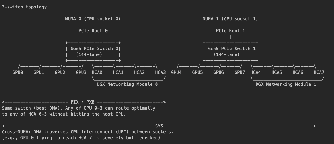
- DGX H100: 2-switch topology. GPU0, GPU1, GPU2, GPU3 share one PCIe switch, while GPU4, GPU5, GPU6, GPU7 share another PCIe switch.
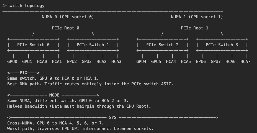
- OEM HGX with 4-switch topology: GPU0, GPU1 shares on PCIe switch. GPU2, GPU3 shares another PCIe switch. GPU4, GPU5 shares another PCIe switch. GPU6, GPU7 shares the last PCIe switch.
- 8-switch 1:1 topology: Each GPU has its own PCIe switch, with a total of 8 PCIe switches.
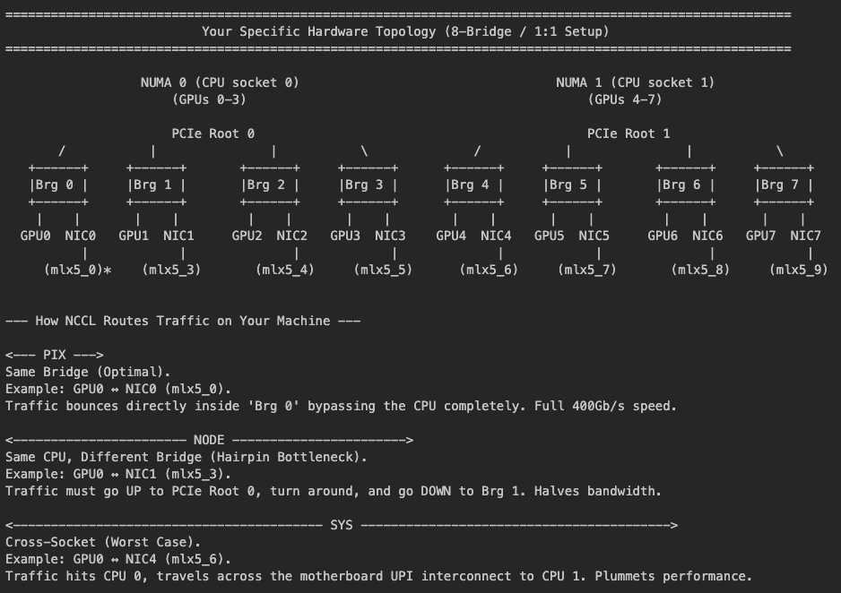
The command to display the hardware topology matrix is:
nvidia-smi topo -m
How to interpret the results of nvidia-smi topo -m
To determine if you are on an official NVIDIA DGX H100 (2-switch), a 3rd-party OEM HGX (4-switch), or a 1:1 8-switch topology, you need to look at the intersection of GPU 0 and NIC 2 (usually labeled mlx5_2 or similar).
Case A: You are on a DGX H100 (2-Switch Topology)
In a DGX, the first 4 GPUs and the first 4 NICs are all under the same single switch.
Look at the cell for GPU 0 and NIC 2: It will say
PIXorPXB.Meaning: GPU 0 can reach NIC 2 without going through the CPU. All four NICs on that NUMA node are equally "close" to all four GPUs.
Case B: You are on an OEM HGX (4-Switch Topology)
In an OEM system (like Supermicro or Dell), the first 4 GPUs are split across two switches.
Look at the cell for GPU 0 and NIC 2: It will say
NODE.Meaning: GPU 0 is on Switch A, but NIC 2 is on Switch B. To talk to each other, the data must travel up to the CPU Root Complex and back down. This is the "hairpin" that halves your bandwidth.
I shall leave Case C as an exercise for the reader.
(Nerd trivia: If you run nvidia-smi topo -m on a DGX H100, the connection between a GPU and its local network module often shows up as PXB instead of PIX. PIX means a single PCIe bridge, while PXB means multiple bridges. This happens because the ConnectX-7 interface itself contains an integrated PCIe bridge, meaning the data traverses the main motherboard PCIe switch AND the ConnectX-7 switch, but it still successfully bypasses the host CPU).
Question: Does this mean the connection between pairs of GPUs within a DGX node over the NVLink is not equal?
Answer: No. Over NVLink, the connection is perfectly equal and ideal across all pairs of GPUs. Do not confuse PCIe topology for NVLink topology.
1. The NVLink Network (GPU-to-GPU) = Perfectly Equal
For any communication strictly within the same 8-GPU node, data travels over NVLink, entirely bypassing the PCIe tree and the CPUs by using a non-blocking NVSwitch crossbar.
Because of this crossbar, GPU 0 talking to GPU 1 takes the exact same path (GPU -> NVSwitch -> GPU) as GPU 0 talking to GPU 7.
Result: Every single GPU pair has the exact same latency and the exact same massive 900 GB/s bidirectional bandwidth. It is a perfectly flat, symmetric, all-to-all relationship.
2. The PCIe Network (GPU-to-NIC / GPU-to-CPU) = Highly Asymmetric
The diagram with a 4-and-4 split is the PCIe tree. This network is only used when data has to talk to something other than another GPU in the same box.
When does it matter? It matters immensely for Inter-node scaling (talking to GPUs in a completely different server).
To talk to a different server, the data must leave the GPU, go up the PCIe tree to a ConnectX-7 HCA (Network Card), and go out over the InfiniBand cables.
This is where the topology matters: If GPU 0 needs to send data over the network, it must use HCA 0, 1, 2, or 3. Because they share
Gen5 PCIe Switch 0, the data flows perfectly (GPU0 -> PCIe Switch -> HCA0).The catastrophic mistake: If the software is misconfigured and tells GPU 0 to route its network traffic out of HCA 7, the data has to travel: GPU0 -> PCIe Switch 0 -> CPU 0 -> CPU Interconnect (UPI) -> CPU 1 -> PCIe Switch 1 -> HCA 7. This creates a massive bottleneck, crushing your cluster's performance.
In short...
Intra-node (Inside the box): Handled by NVLink. All GPUs are equal peers. No NUMA issues, no PCIe bottlenecks. 100% symmetric.
Inter-node (Outside the box): Handled by PCIe + HCAs. Highly asymmetric. You must strictly pair GPUs to their local network cards (NUMA affinity) to maintain high bandwidth.
When NCCL (NVIDIA Collective Communications Library) does an AllReduce across a 1,000-GPU cluster, it knows to use the flat NVLink crossbar to shuffle data inside the 8-GPU nodes, and then carefully pairs specific GPUs to specific local HCAs via PCIe to blast that data out to the rest of the cluster.
PIX, NODE, SYS — what the distances mean
When a GPU needs to send data through an HCA via DMA, the data travels through the PCIe tree. The shorter the path, the lower the latency:
| Distance | Path taken | Performance impact |
|---|---|---|
| PIX | GPU → Bridge → HCA (same bridge, no root traversal) | Best — shortest DMA path |
| NODE | GPU → Bridge → PCIe Root → Bridge → HCA (same NUMA, different bridge) | ~2x slower |
| SYS | GPU → Bridge → Root → CPU interconnect → Root → Bridge → HCA (cross-NUMA) | Worst — crosses socket boundary |
NCCL auto-detects this topology and preferentially uses PIX-affine HCAs. You don't need to configure this — but forcing only NODE-distance HCAs halves bandwidth.
PIX-affine mapping
With 8 GPUs and 8 HCAs (1:1 ratio), each GPU has its own PIX-affine HCA on the same PCIe bridge. The specific mlx5 device names vary per node (different PCIe layouts), but NCCL auto-detects the mapping — no per-node config needed.
6. The Software Stack
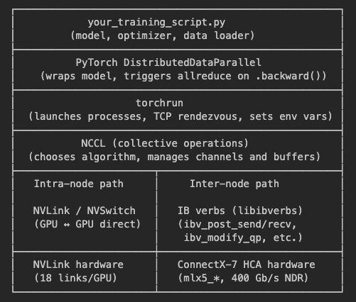
torchrun is the launcher. It starts N processes per node, assigns each a rank, and sets up a TCP rendezvous so all ranks can find each other. It does not use MPI, PMIx, UCX, or SLURM — it has its own TCP-based coordination.
NCCL is the communication library. When PyTorch DDP calls allreduce, NCCL decides:
Which transport to use (NVLink for intra-node, IB for inter-node)
Which algorithm (Ring, Tree, or auto)
Which HCAs and how many QPs per connection
IB verbs (libibverbs) is the userspace API for talking to InfiniBand hardware. NCCL calls ibv_* functions directly — it does not go through the kernel TCP/IP stack for data transfer.
7. The Three Networks
Our cluster has three distinct network paths. Understanding which one carries what traffic is key to debugging:
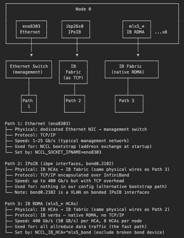
Key insight: Paths 2 and 3 use the same physical InfiniBand wires but different protocols. IPoIB wraps TCP/IP packets for compatibility; native IB RDMA uses the hardware directly at full speed. NCCL uses Path 3 for data.
What is a VLAN?
bond0.2102 is a Virtual LAN — a logical partition on a network interface. The .2102 is a VLAN tag that separates traffic into isolated segments on the same physical link. Multiple VLANs (2102, 3102, 4090) can share one bonded interface, each carrying different traffic types. In our cluster, the VLANs are on bonded IPoIB interfaces — but NCCL doesn't use any of them.
What is mlx5_bond_0?
A bonded (aggregated) IB device created by the driver. It has lid=0x0 (no valid IB address) and pkey=0xffff (default partition, different from the real HCAs' 0x9002). It exists for IPoIB but is invalid for RDMA QP connections. NCCL must be told to exclude it via NCCL_IB_HCA=^mlx5_bond.
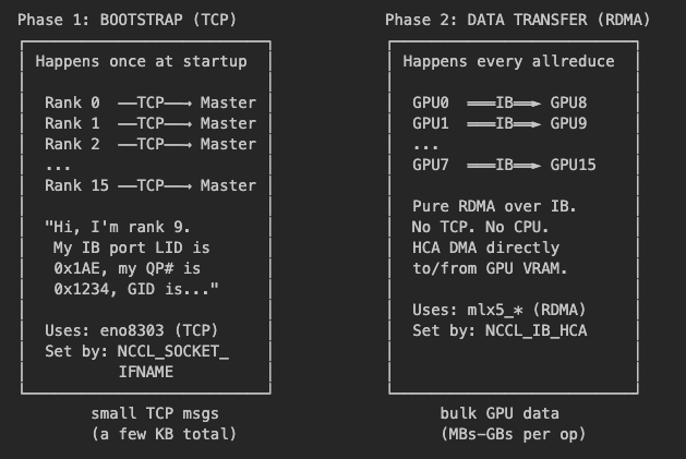
8. How NCCL Bootstraps and Transfers Data
NCCL communication happens in two distinct phases. This is the most important conceptual distinction for debugging:
QP State Machine
Before RDMA data can flow, each Queue Pair must be initialized through a state machine.
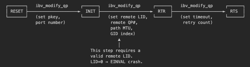
RESET → INIT: Configure local port and partition key.
INIT → RTR: Set remote destination — LID, QP number, MTU, GID.
RTR → RTS: Set retry parameters. After this, the QP can send and receive data.
9. How Allreduce Works
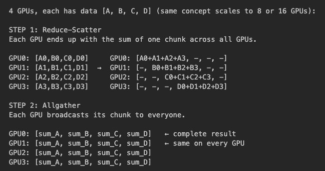
Allreduce computes the sum (or average) of a tensor across all GPUs and distributes the result back to everyone. NCCL breaks this into two phases:
Reduce-Scatter + Allgather
BusBW: What NCCL Reports
NCCL reports BusBW (bus bandwidth), a normalized metric — not a direct measurement of physical link speed. To allow consistent comparisons across different cluster sizes and topologies, NCCL always calculates BusBW using the following formula:
BusBW = AlgBW x 2 x (n - 1) / n
The
x 2accounts for reduce-scatter + allgather (two phases, each moving data)The
(n-1)/naccounts for the fact that in a ring, each GPU sends a fraction of the total data
Source: https://github.com/NVIDIA/nccl-tests/blob/master/doc/PERFORMANCE.md
IB bandwidth sweep (4-GPU x 2 nodes, 4 PIX-affine HCAs, 200 GB/s ceiling)
| Algorithm | BusBW | vs Ring ceiling | vs Hierarchical ceiling (350 GB/s) | Interpretation |
|---|---|---|---|---|
| Ring | 191 GB/s | 95.5% | — | Actual IB utilization: ~48 GB/s per HCA, 96% of NDR line rate |
| Tree | 288.8 GB/s | 144% | 82.5% | Hierarchical reduction — IB carries ~1×S instead of 1.75×S |
| Auto | 328.8 GB/s | 164% | 93.9% | Hierarchical and/or SHARP — near-perfect IB utilization under reduced data volume |
The Ring result (191 GB/s) is the ground truth for physical IB link speed. The Auto result (328.8 GB/s) is 93.9% of the hierarchical ceiling (350 GB/s) — excellent utilization, possibly due to a reduced data volume, not a faster link.
Ring vs Tree vs Auto
Ring: The baseline. Data travels in a circle; every GPU's transmit and receive links are fully utilized. BusBW directly equals physical link speed. Most robust but slowest for multi-node (191 GB/s in our tests).
Tree: Uses hierarchical reduction — reduces intra-node first (NVLink), then sends only the result inter-node (IB). We hypothesize that because the tree algorithm cuts IB data volume by ~1.75x, so BusBW reports higher than the physical ceiling (288.8 GB/s). The IB links are not running faster; they're carrying less data.
Auto (may use CollNet/SHARP): NCCL selects the best algorithm. On clusters with SHARP-capable IB switches, it may use CollNet, where the switch ASIC performs the reduction in hardware. If SHARP is not available, Auto typically uses an optimized hierarchical tree. We hypothesize that because BusBW reflects "equivalent ring performance" — not physical wire speed (329 GB/s in our tests, 93.9% of the 350 GB/s hierarchical ceiling).
10. The Container Layer: enroot
The training runs inside enroot containers, which isolate the process from the host. This creates a critical requirement: InfiniBand hardware devices must be explicitly mounted into the container.
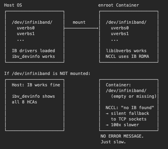
MELLANOX_VISIBLE_DEVICES
The enroot hook at /etc/enroot/hooks.d/50-mellanox.sh reads this variable during container start to decide which IB devices to mount. Setting it inside a running container does nothing.
# Correct — set BEFORE container starts:
MELLANOX_VISIBLE_DEVICES=all enroot start mycontainer

# Useless — container already running, hook already ran:
export MELLANOX_VISIBLE_DEVICES=all   # too late
If /dev/infiniband is already present in the container, you don't need this variable.
11. Putting It All Together: End-to-End Flow
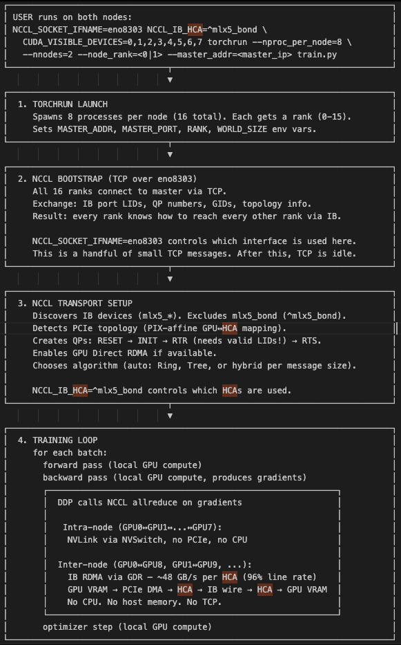
Here is the complete sequence from launching training to a completed allreduce:
12. Quick Reference
At the end of our debugging, we realised what we needed to do was to include the following in our enroot start command. The added command mounts /dev/infiniband properly in the container, without which NCCL will ignore NCCL_IB_HCA entirely and falls back to sockets.
enroot start \ ... \ -m /dev/infiniband:/dev/infiniband \ # <-- ADD THIS -r -w \ trainer
Within the enroot container, the 3 Required Environment Variables that we found which worked for us:
| Variable | What it does | Why it's needed |
|---|---|---|
NCCL_SOCKET_IFNAME=eno8303 |
Tells NCCL to use the Ethernet management NIC for TCP bootstrap | Without it, NCCL might pick an interface that can't reach the other node |
NCCL_IB_HCA=^mlx5_bond |
Excludes mlx5_bond_0 from NCCL's HCA list |
mlx5_bond_0 has LID=0 which crashes QP setup with EINVAL |
CUDA_VISIBLE_DEVICES=0,1,2,3,4,5,6,7 |
Limits PyTorch to the 8 GPUs | Prevents picking up non-existent or unintended devices |
Everything else — GDR, algorithm selection, QPS, HCA affinity — NCCL handles optimally by default.
13. Now back to the environment variables mentioned at the beginning of this article...
Do I need PMIX_MCA_psec=^munge?
Only if launching via srun or mpirun with PMIx. PMIx is a process management interface used by SLURM and MPI. ^munge excludes the munge authentication plugin, which fails when munge isn't configured inside the container. torchrun uses its own TCP-based rendezvous and doesn't touch PMIx, so this variable is unnecessary.
Do I need UCX_NET_DEVICES?
UCX is an alternative transport layer used by some MPI implementations (like OpenMPI built with UCX support). NCCL has its own IB plugin and doesn't use UCX — it has NCCL_IB_HCA for the same purpose. Only matters if your launcher uses MPI with UCX for its control plane, which torchrun does not.
Do I need MELLANOX_VISIBLE_DEVICES=all?
Only at container start time, and only if /dev/infiniband isn't already mounted. This is an enroot container runtime variable — the Mellanox hook (/etc/enroot/hooks.d/50-mellanox.sh) reads it during enroot start to decide which IB devices to mount. Setting it inside an already-running container does nothing. If /dev/infiniband is already present, you don't need it.
Correct usage (on the host, during container start):
MELLANOX_VISIBLE_DEVICES=all enroot start ...
What does NCCL_SOCKET_IFNAME actually control?
Only the bootstrap phase. When NCCL starts, GPUs across nodes don't know about each other — they don't know which IB ports, LIDs, or QP numbers to connect to. Bootstrap is the initial setup where all ranks exchange this connection information over plain TCP sockets:
Bootstrap: All ranks connect to the master via TCP (using
NCCL_SOCKET_IFNAME), exchange IB addresses (LIDs, QP numbers, GIDs)RDMA setup: Each rank uses the exchanged info to create IB queue pairs and establish direct RDMA connections
Data transfer: All actual allreduce/broadcast traffic flows over IB RDMA — TCP is no longer used
So NCCL_SOCKET_IFNAME only controls step 1 — a handful of small TCP messages at startup. After that, all data moves over IB verbs and the TCP interface is idle.
Should I use NCCL_SOCKET_IFNAME=ibp instead of eno8303?
Either works. ibp prefix-matches the IPoIB interfaces (ibp26s0, ibp60s0, etc.) which run TCP over the IB fabric. eno8303 is the Ethernet management network. Since bootstrap is just a few small messages, the choice makes no measurable difference (329.0 vs 328.7 GB/s in our tests). eno8303 is slightly cleaner because it keeps TCP control traffic on a separate physical network from RDMA data traffic.
What is bond0.2102 vs eno8303?
Two different networks:
eno8303 (198.21.151.x) — Dedicated Ethernet management network. A physical interface directly to the cluster management switch.
bond0.2102 (198.21.3.x) — A VLAN (2102) on a bonded interface built on top of IB interfaces using IPoIB (IP-over-InfiniBand). TCP traffic here shares the same IB fabric as RDMA data transport.


